Heavy Gage OSL All-Bolted Clip Angles
- General Overview
- Tips and Tricks
- Related Tools
To specify this type of standard clip angle in the model :
- Heavy Gage OSL All-Bolted Clip Angles are double clip angles that shop bolt to the supported or supporting member and are designed as the supported beam's end connection when ' Heavy Gage ', ' Bolted ' (to supported), ' Bolted ' (to supporting), and shop attach to ' Supported ' (or 'Supporting') are set in "
 Connection specifications " for auto standard , user defined or beam-window-specified clip angles.
- For a joist, the required settings that result in a clip angle being designed using this clip angle configuration are ' Heavy Gage ', ' Bolted ' (to supported), and ' Bolted ' (to supporting).
- Clip angles can also be used for the attachment of vertical brace and horizontal brace gusset plates in various framing situations. For vertical brace to beam & column framing situations, connection design attaches the vertical brace gusset plate to the column using the same clip angle configuration that is used to attach the beam to the column. A " Combine beam/vbrc clip angles " option in the beam's connection specifications lets you specify whether or not those clip angles are combined.
 or
or 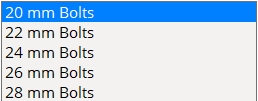
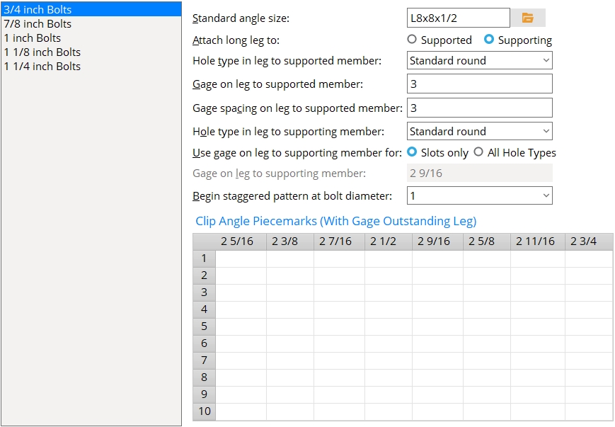
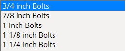
| Each bolt diameter is a different clip angle configuration that must be set up separately. The list box shows Imperial sizes when the " Available Bolt Diameters " is 'Imperial '. Metric sizes are displayed when the " Available Bolt Diameters " is set to 'Metric '. If " Available Bolt Diameters " is set to 'Both ', the primary dimensioning "Units" will determine whether the list box shows Imperial or Metric bolt sizes. |
Standard angle size: The angle section size for the specific bolt diameter that has been selected in the list box. The angle must be listed in the local shape file.
To enter an angle section size: Either type in the section size that you want (e.g., ' L4x3 1/2x5/16 '), or press the "file cabinet" browse button (
) and choose an angle section from the list of angles in the local shape file .
Attach long leg to: Supported or Supporting . This applies when a " Standard angle size " with unequal legs has been entered.
Select ' Supported ' if you want the long leg of the angle to bolt to the supported beam or the knife plate of the joist.
Select ' Supporting ' if you want the long leg of the angle to bolt to the supporting beam or column.
Hole type in leg to supported member: Standard round or Short slot or Long slot or Oversized or User slot #1 or User slot #2 .

Gage on leg to supported member: The distance from the face on the outstanding leg of the clip angle to the center of the first column of holes on the leg that bolts to the web of the supported beam.
Gage spacing on leg to supported member:
' 0 ' (zero) causes heavy gage clip angles of the specified " Standard angle size " and bolt diameter to be designed with only one column of bolts.
A ' distance ' results in two columns of bolts that are spaced that distance from center-to-center in the bolted heavy gage clip angle.
Validation: If you enter a " Gage spacing " that is less than 2.75 times the selected bolt diameter and press the Tab key, validation gives you the following warning, " The gage spacing is below the minimum gage required by AISC standards ."
Hole type in leg to supporting member: Standard round or Short slot or Long slot or Oversized or User slot #1 or User slot #2 .
Use gage on leg to supporting member for: ![]() Slots only or
Slots only or ![]() All hole types .
All hole types .
'
Slots only ' instructs connection design to apply the " Gage on leg to supporting member " only when the " Hole type in leg to supporting member " is ' Short slot ' or ' Long slot ' or ' User slot #1 ' or ' User slot #2 '. On standard round holes, the gage is set based on the " Heavy gage, inside holes " center-to-center distance and the web thickness of the supported beam (or the thickness of the joist's knife plate).
'
Gage on leg to supporting member: The distance from the outside face of the clip angle to the center of the first column of slots on the leg that bolts to the supporting beam or column.
For slots, connection design may apply a different GOL than that which is entered here in order to permit bolts to fit in the slots at the "Heavy gage, inside holes" center-to-center distance.
Begin staggered bolt pattern at bolt diameter: The minimum diameter at which bolt patterns are to be staggered.
To make an entry: You can type in a diameter, or select a bolt diameter from the menu (
). Diameters listed on the menu come from Home > Project Settings > Job > Bolts, Washers, and Holes > Bolt Settings > the " Available bolts " list.
Clip Angle Piecemarks
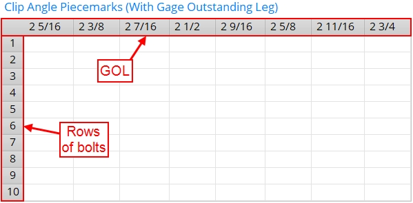
When connection design creates a clip angle that exactly matches a clip angle defined in the Clip Angle Piecemarks table, SDS2 piecemarking assigns the piecemark that is entered for that clip angle. Both the GOL and the number of rows must match exactly.
Note : To edit the Clip Angle Piecemarks table, your current Fabricator must be the Master Fabricator. This ensures that standard piecemarks for clip angles come from a single setup source, regardless of your current Fabricator.
For clip angles in this configuration: The GOL is set according to the " Heavy gage, inside holes " center-to-center distance plus the web thickness of the supported beam (or the joist's knife plate thickness). If a standard piecemark from this table matches the GOL and number of rows of bolts in the actual designed clip angle, that piecemark is assigned.
Column heads (GOLs): Each column head on this table is a GOL (gage on outstanding leg). These GOLs are calculated from the "Heavy gage, inside holes" center-to-center distance that is entered in Clip Angle Settings .
Rows: Each row on the Clip Angle Piecemarks table is a number of rows of bolts in the clip angle.
To make entries: Click the cell that corresponds to the GOL (gage on outstanding leg) and the number of rows of bolts desired. Type in a clip angle standard piecemark of up to 61 characters.


|
|
OK (or the Enter key) closes this screen and applies the settings.
Cancel (or the Esc key) closes this screen without saving any changes.
Reset undoes all changes made to this screen since you first opened it. The screen remains open.
- Settings applied here are for your current Fabricator . Each Fabricator in your current Job is a different collection of settings.
- To edit the Clip Angle Piecemarks table on this screen, your current Fabricator must be the Master Fabricator, otherwise this table is disabled .
- If your current Fabricator is not the Master Fabricator, the piecemarking routine will continue to reference the version of the Clip Angle Piecemarks table in the Master Fabricator.
- If the Clip Angle Piecemarks table on this screen is filled out, any standard piecemark from the table can be added as an existing material .
- Red or yellow exclamation point icons
 or
or 
- Clip angle input specs (settings for clip angles)
- Setup of clip angle connections (index)
- Clip Angle Settings

